FOUNDATION EDUCATION PORTAL
CUSTOM FOUNDATION SUPPORT
Coastal Foundation Solutions experience in ground improvement and development of innovative pile designs provides clients cost-effective design build solutions.
The basics in designing any foundation starts with the weakest link, which is predominantly the soil. Consequently, it is greatly recommended to commence with a geotechnical analysis (soil borings) before designing any project. Once soil data is secured, a geotechnical engineer may provide pile recommendations based on subsurface soil conditions.
Geotechnical conditions and the structural design of the helical pile will impact the pile capacity. Helical piles are designed so most of the capacity of the pile is generated through the bearing of the helix plates against the soil. Shaft friction is not a contributing factor to a helical piling unless it is a grouted pile. Consequently, ground conditions and the pile design itself are significantly important.
As new project designs are implemented within complex environments, the essential geotechnical plans and structural blueprints are also more complex predictably requiring multiple services. The advent of the Surfside Tower collapse in Miami and Hurricane Ian has design professionals strongly securitizing foundation projects.
ENGINEERING EXPERTISE
Structural designers and engineers need to contemplate the following dynamics when designing for specifics and its foundations:
- Geotechnical examination and interpretation to predict soil conditions.
- Engineered design for foundations based on load specifications and soil profiles.
- Pile analysis to establish pile capacities for specific soils.
- Provide custom piles and assemblies for specific projects.
- Engineered structural components to provide interconnectedness between concrete foundation and piling.
- Piling corrosion life span determination
- Engineered drawings and as-built drafting documentation.
- P.E. stamped calculations and pile design.
- Pile monitoring services to certify pile installations and load testing.
The design professional has a new pile option to consider when designing a pile supported structure in Florida.
We can also contact our network of national product teams to provide engineered support for complex piling requirements. Our local and regional ground knowledge enables us to create and target optimal solutions for pile supported projects.
PILE LOAD TESTING
The only way to truly confirm site-specific helical pile capacity is by conducting a full-scale load test. Load tests verify ultimate pile performance by confirming the relationship between applied loading and pile head movement over a specified period. Ultimate helical pile capacity is the maximum load attained when either plunging of the screw pile occurs or when the net deflection surpasses 10% percent of the average helix plate diameter, whichever occurs first. Final pile deflection is defined as the total pile head deflection minus the flexible lengthening or shortening of the shaft.
Static Load tests for helical piles are no further complicated than load tests for other deep foundations systems, and in similar configurations, are less expensive. The other attribute of helical/screw piling is their minimal impact on the construction site and schedule. Load tests allow engineers to develop more efficient designs, provide significant cost savings with modified piling designs, and reduce project time. Even without a potential overall cost savings, load tests provide design professionals, and clients with an increased understanding of helical pile performance.
The in-field piling load test provides engineers confidence that helical piles will perform as anticipated, often time with higher capacities then anticipated.
Project owner’s and their design professionals favor a foundation option that minimizes construction traffic, site interruption, and surrounding neighbors.
A Helical Pile Is a Deep Foundation Solution Newly engineered helical piles are designed for supporting light residential structures, to heavy offshore oil platforms. Helical or screw piling are designed to sustain compressive loads more than (400 KPS) from small stairs to a 30-story tower. Their tension capacity mirrors compressive strength in most categories.
In other parts of the world a common name for a helical piling is “screw pile”.
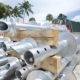
A helical pile consists of a round steel shaft or a solid square shaft. The diameter of the pipe piles and square shaft piles increase in size as the required capacity of the piles intensify. Typically, one or more helix bearing plates are welded to the shaft. The length, thickness and diameter of a helixes varies based on several factors as will the number, thickness, and diameter of helixes.
Helical piles present a less intrusive and more time-effective substitute to traditional concrete piles and auger cast piling.
Helical piles are the perfect solution for building foundations, environmentally sensitive sites, temporary structures, underpinning, and sheet piling walls. The piles can be used as solid foundations for many applications, due to their quiet method of installation, extensive uplift capability, and smaller installation equipment.
Helical pile or grouted micro pulldown pile installation is exclusively well suited for foundation conditions where increased competency is requested.
COASTAL CORROSION PROTECTION
Florida’s corrosive environment threatens non-treated pipe pile deterioration and weaking of non-galvanized piling, as salt soils are particularly corrosive, the piling may prematurely age. Consequently, piles installed within coastal areas should be hot dipped galvanized or of suitable thickness to provide a 100-year longevity factor. The hot-dip galvanized coating process creates a second line of defense against corrosion.
APPLICATION OF SCREW PILES
Helical piles are an excellent choice where the soil near the surface has become too weak to support a structure. Screw/Helical piles can also be used where the soil profile, dimensions and location of the structure cannot be supported by alternative foundation pile methods.
EXEMPLARY FOUNDATION SUPPORT
Helicals are used to provide support to structures that include the following:
- Waterfront Homes, Industrial Buildings, and Commercial Structures
- Marine Applications: Bridges, Seawalls, and Jetties
- Transmission Towers
- Wind Generation Turbines
- Modular Buildings
- Traffic Signal Gantries
- Utility and Oil Transmission Pipes
- Stabilization of Existing Foundations
- Temporary or Permanent Support for Re-Levelling of Existing Structures
- Sustenance Capacity Improvements
- Emergency Response to Building Damage from Hazards such as Hurricanes, Inclement Weather or Flooding
- Support for Existing or New Retaining Structures
- Marine Tiebacks
- Stabilization for Slopes
- Rapid Response Required Time Frame
- Interim Securing of Machinery (Specifically Against Uplift)
PILE SPACING & GROUPING INFLUENCE
Helical Piling design usually depicts how the pile foundations are acting as a single pile unit or as a piling group. This is especially relevant when piles are spaced closer than 3-4 helix (36” to 42”) diameters apart or where there is a compressible soil layer underlying the initiating layer.
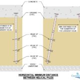
Piles installed near to another pile, churn the soil, creating a loss of torsional compressive capacity. Alternate options exist to negate the process of churning. Erecting a screw pile in slight batter may be one way of accomplishing increased pile separation (distance) and preserving the tension and compression capability. A round shaft or square bar piling installed at a 5 degree batter provides adequate separation between pilings. The piles travel further apart in batter configuration, allowing for required pile separation distance.
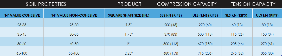
SQUARE SHAFT HELICALS
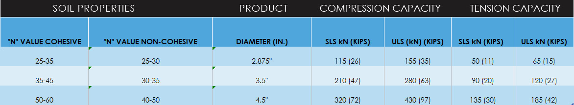
ROUND SHAFT HELICALS
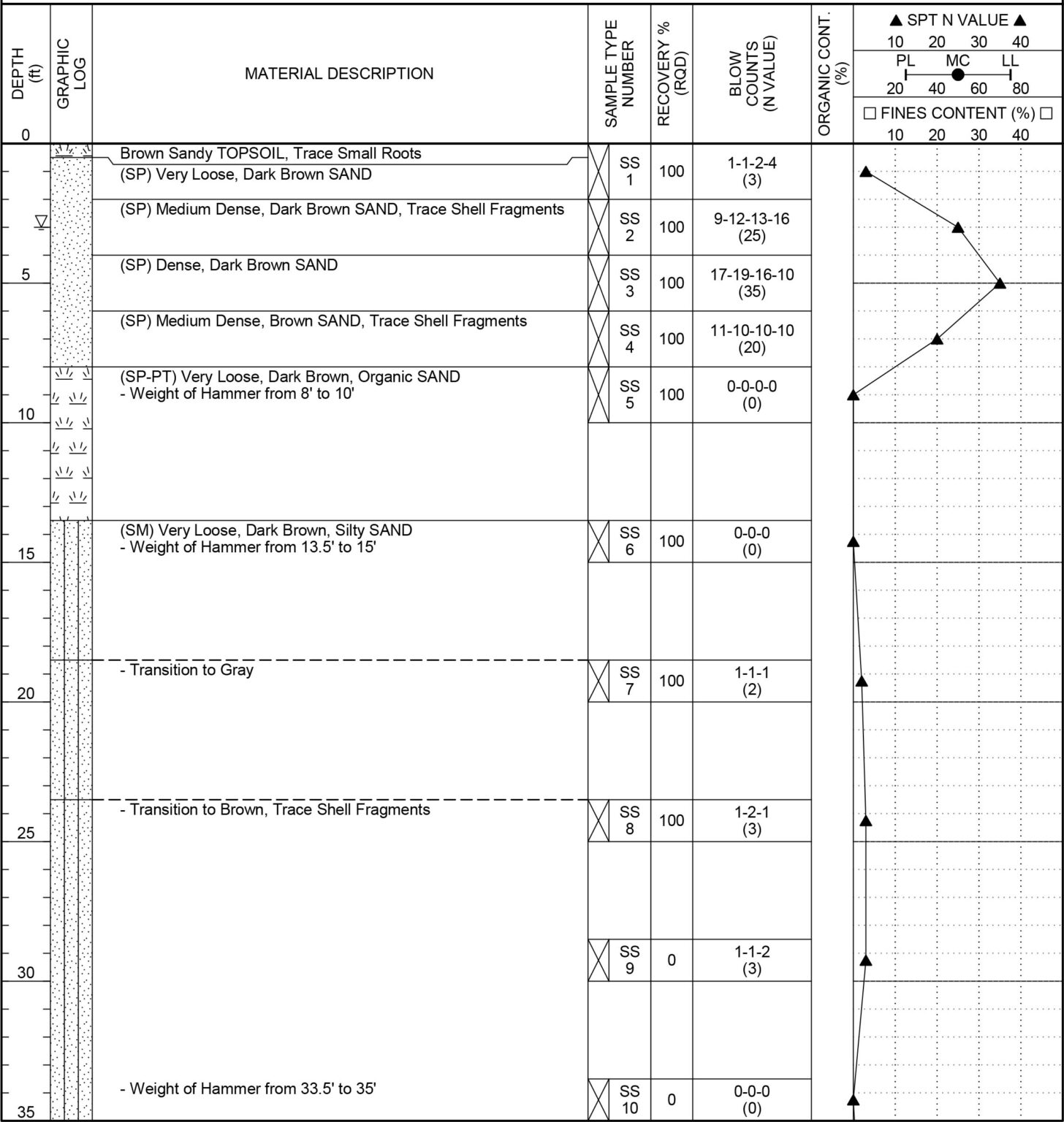
SOIL CONDITIONS MATTER
Installing Helical Piles into hard rock can create a spin out (Refusal) without penetration into the rock layer. In these instance’s the torque capacity is no longer defined or measured. The digital torque indicator will no longer secure torque values as the pile is presenting no resistance and churning on rock. If the solid rock cannot be penetrated, alternative piling solutions will need to be entertained such as changing to micro pulldown pilings or grouted hollow bar piles.
Helical piles are best suited for ground conditions with progressively increasing soil strength or where there is a gradual weathering profile above the top of rock layer. In these surroundings, it is much more likely that the helix’s will be totally seated, that is, the helix’s will be imbedded within the surrounding layer. This creates torsional values which are transmitted to our torque correlation equipment, providing real pile capacity.
LIQUEFIABLE & WEAK SOILS
Helical pile shafts are more slender than other types of pile foundations rendering them more disposed to buckling in poorly supporting soils. When a helical piling is required to travel through deep deposits of weak soils and/or liquefiable soils, there is an increased risk of shaft buckling. Consequently, the helical pile must be designed to overcome this situation by increasing shaft diameter or the addition of an external grout column.
THE PROCESS
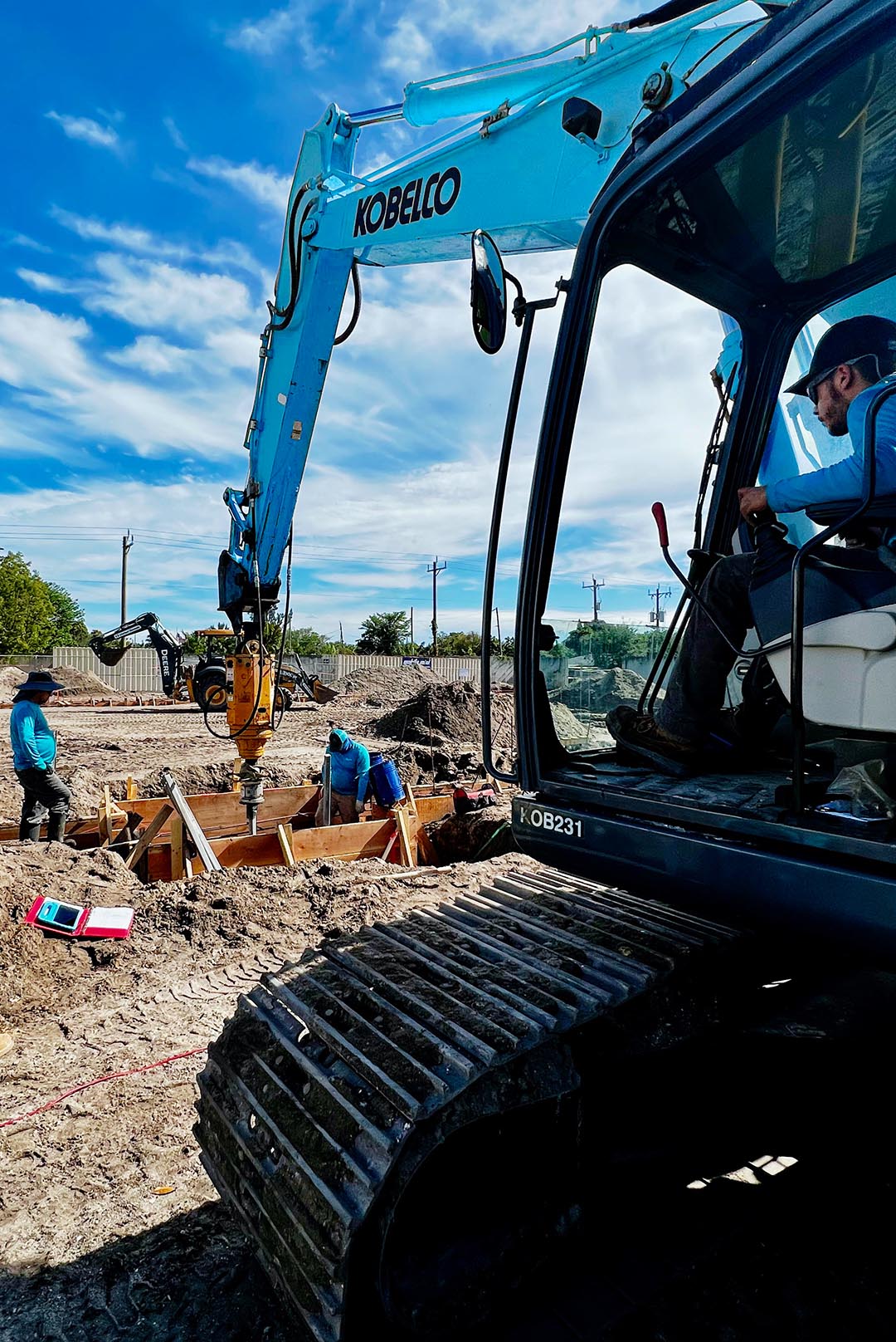
A galvanized steel helical piling is commonly used where the soil profile is not resilient enough to support a concrete spread footer or structure. The installation technique of a helical pile is quite simple. Helical piles are rotated into the ground, much like a wood screw or large lag bolt.
With the use of a competent size excavator, a hydraulic anchor drive is employed to apply the substantial torque that is required to screw a helical pile into the ground. The pile travels to a point where it finds a strong resilient soil profile capable of supporting the structure and meeting engineered capacity (The pile is screwed into the ground not augured).
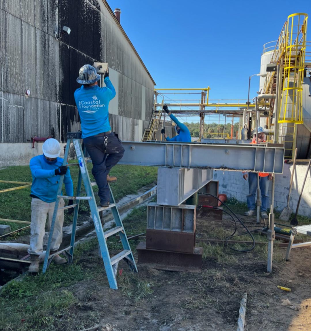
Once the helical pile is installed, a cut off elevation is determined using the architectural plans. The pile works in conjunction with a concrete footer or grade beam to provide the engineered designed capacities. There are various configurations of steel termination plates added to the top of helical piles dependent on pile capacities. The most common engineered termination plate is 8” x 8” x ½” thick steel plate either bolted or welded unto an extension segment.
Helical/Screw piles are installed with smaller, standardized equipment, it maintains a very compact, and quiet installation process. In addition, there are never any messy or contaminated spoils to deal with. The pile provides ideal foundation support for sites where there might be low clearance, low overhead conditions, or on site restrictions.
The selection of hydraulic anchor drives, and handling excavator is ultimately determined by:
- Shaft Torsional Capacity
- Site Access Limitations (Interior Pile Locations)
- Confined Locations
- Soil Profiles
- Situational Tolerances.